

How To Use Black Eye Orb

Graphical center design showing an example of two power levels in an OOK modulation scheme. Constant binary 1 and 0 levels are shown, as well as transitions from 0 to 1, 1 to 0, 0 to i to 0, and 1 to 0 to 1.
In telecommunication, an eye pattern, too known equally an eye diagram, is an oscilloscope display in which a digital signal from a receiver is repetitively sampled and applied to the vertical input, while the data charge per unit is used to trigger the horizontal sweep. Information technology is then called considering, for several types of coding, the pattern looks like a series of optics between a pair of rails. It is a tool for the evaluation of the combined furnishings of channel dissonance, dispersion and intersymbol interference on the performance of a baseband pulse-transmission system. The technique was commencement used with the WWII SIGSALY secure oral communication manual organisation.
From a mathematical perspective, an middle blueprint is a visualization of the probability density function (PDF) of the signal, modulo the unit interval (UI). In other words, it shows the probability of the indicate beingness at each possible voltage across the duration of the UI. Typically a colour ramp is practical to the PDF in order to make small-scale effulgence differences easier to visualize.
Several system performance measurements can be derived past analyzing the brandish. If the signals are likewise long, too short, poorly synchronized with the system clock, also high, also low, as well noisy, or too tiresome to change, or have too much undershoot or overshoot, this can be observed from the eye diagram. An open up eye pattern corresponds to minimal signal baloney. Distortion of the betoken waveform due to intersymbol interference and noise appears equally closure of the centre design.[1] [2] [three]
Calculation [edit]
Source data [edit]
The start step of calculating an eye pattern is normally to obtain the waveform beingness analyzed in a quantized form. This may be done past measuring an actual electrical system with an oscilloscope of sufficient bandwidth, or by creating synthetic data with a circuit simulator in club to evaluate the signal integrity of a proposed design. A combination of the two approaches may be used likewise: simulating the furnishings of an arbitrary excursion or transmission line on a measured signal, perhaps to decide whether a betoken will however be intelligible afterwards passing through a long cablevision. Interpolation may likewise exist applied at this time in social club to increment the number of samples per UI and produce a shine, gap-free plot which is more visually appealing and easier to understand.
Slicing [edit]
Next, the position of each sample within the UI must be determined. There are several methods for doing this depending on the characteristics of the signal and the capabilities of the oscilloscope and software in utilize. This step is critically important for authentic visualization of jitter in the eye.
Triggering [edit]
A very elementary method of slicing is to set the oscilloscope display to exist slightly more than 1 UI wide, trigger on both rising and falling edges in the betoken, and enable display persistence so that all measured waveforms "stack" into a single plot. This has the advantage of being possible on almost whatever oscilloscope (fifty-fifty fully analog ones) and tin can provide decent visualization of noise and overall signal shape, but completely destroys the jitter content of the signal since the instrument's trigger re-synchronizes the plot to each UI. The only jitter visible with this method is that of the oscilloscope itself, as well as extremely loftier frequency jitter (frequencies with menstruum less than the UI).
Fixed rate [edit]
A elementary manner to take the eye pattern display jitter in the indicate is to guess the symbol rate of the signal (perhaps by counting the boilerplate number of zero crossings in a known window of time) and acquiring many UIs in a unmarried oscilloscope capture. The showtime aught crossing in the capture is located and declared to be the outset of the first UI, and the residual of the waveform is divided into chunks 1 UI long.
This approach can work adequately for stable signals in which the symbol charge per unit remains exactly the same over time, however inaccuracies in the system mean that some migrate is inevitable and then information technology is rarely used in practice. In some protocols, such as SATA, the symbol rate is intentionally varied by use of spread spectrum clocking, so bold a fixed charge per unit will atomic number 82 to the centre grossly exaggerating the actual jitter nowadays on the point. (While spread spectrum modulation on a clock is technically jitter in the strict sense, receivers for these systems are designed to rail the modulation. The only jitter of interest to a betoken integrity engineer is jitter much faster than the modulation rate, which the receiver cannot track effectively.)
Reference clock [edit]
With some protocols, such every bit HDMI, a reference clock is supplied along with the betoken, either at the symbol rate or at a lower (but synchronized) frequency from which a symbol clock can be reconstructed. Since the actual receiver in the system uses the reference clock to sample the data, using this clock to decide UI boundaries allows the eye blueprint to faithfully display the signal as the receiver sees it: only jitter betwixt the betoken and the reference clock is displayed.
Clock recovery [edit]
Most loftier speed serial signals, such as PCIe, DisplayPort, and well-nigh variants of Ethernet, use a line code which is intended to allow piece of cake clock recovery by ways of a PLL. Since this is how the bodily receiver works, the most accurate way to slice data for the eye pattern is to implement a PLL with the same characteristics in software. Correct PLL configuration allows for the eye to conceal the furnishings of spread spectrum clocking and other long-term variation in the symbol rate which do not contribute to errors at the receiver, while still displaying higher frequency jitter.
Integration [edit]
The samples are so accumulated into a 2-dimensional histogram, with the X centrality representing time within the UI and the Y axis representing voltage. This is then normalized by dividing the value in each histogram bin by the value in the largest bin. Tone mapping, logarithmic scaling, or other mathematical transformations may exist practical in order to emphasize dissimilar portions of the distribution, and a color slope is applied to the concluding eye for display.
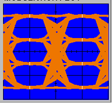
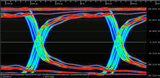
Large amounts of data may exist needed to provide an accurate representation of the signal; tens to hundreds of millions of UIs are ofttimes used for a single eye design. In the example beneath, the eye using twelve thousand UIs but shows the basic shape of the middle, while the eye using eight million UIs shows far more than nuance on the rise and falling edges.
-

Eye pattern of twelve thousand UIs of a one.25 Gbit/south bespeak
-

Heart pattern of eight million UIs of a 1.25 Gbit/s signal
Modulation [edit]
Each form of baseband modulation produces an eye pattern with a unique appearance.
NRZ [edit]
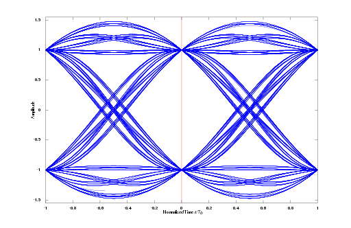
The eye pattern of a NRZ signal should consist of two clearly distinct levels with smooth transitions between them.

Eye pattern of a 1.25 Gbit/south NRZ signal
MLT-3 [edit]
The center blueprint of a MLT-iii betoken should consist of 3 clearly distinct levels (nominally -1, 0, +1 from bottom to peak). The 0 level should be located at zip volts and the overall shape should be symmetric well-nigh the horizontal axis. The +one and -1 states should have equal amplitude. There should be shine transitions from the 0 state to the +1 and -1 states, however at that place should be no direct transitions from the -1 to +ane state.

Eye pattern of a 125 Mbit/southward MLT-3 signal
PAM [edit]
The eye blueprint of a PAM indicate should consist of N conspicuously distinct levels (depending on the PAM guild, for example PAM-4 should accept 4 levels). The overall shape should be symmetric about the horizontal axis and the spacing of all levels should be compatible.
PSK [edit]

Channel furnishings [edit]
Many properties of a channel can be seen in the centre pattern.
Emphasis [edit]
Emphasis practical to a signal produces an additional level for each value of the bespeak which is college (for pre-emphasis) or lower (for de-emphasis) than the nominal value.
The eye pattern for a signal with emphasis may exist mistaken for that of a PAM signal at first glance, notwithstanding closer inspection reveals some central differences. Most notably, an emphasized signal has a express set of legal transitions:
- Stiff state to corresponding weak state (ane-1 or 0-0 bit pattern)
- Strong state to opposite strong state (second transition of a 1-0-1 or 0-ane-0 bit pattern)
- Weak state to opposite strong state (second transition of a 1-1-0 or 0-0-1 bit pattern)
An emphasized signal volition never transition from a weak country to the respective strong state, a weak state to another weak land, or remain in the aforementioned strong state for more than than one UI. A PAM betoken also normally has equally spaced levels while emphasized levels are normally closer to the nominal betoken level.

Eye pattern of a 1.25 Gbps NRZ bespeak with 6 dB of pre-emphasis
High-Frequency Loss [edit]
Loss of printed circuit board traces and cables increases with frequency due to dielectric loss, which causes the channel to behave as a depression-laissez passer filter. The effect of this is an increment in indicate rise/autumn time. If the data rate is high enough or the channel is lossy plenty, the point may not even achieve its full value during a fast 0-1-0 or 1-0-1 transition, and only stabilize subsequently a run of several identical bits. This results in vertical closure of the eye.
The image below shows a 1.25 Gbit/southward NRZ betoken after passing through a lossy aqueduct - an RG-188 coaxial cable approximately 12 anxiety (3.65 meters) in length. This aqueduct has loss increasing in a adequately linear style from 0.1 dB at DC to 9 dB at vi GHz.
The superlative and bottom "runway" of the centre show the final voltage the signal reaches after several consecutive bits with the same value. Since the channel has minimal loss at DC, the maximum signal amplitude is largely unaffected. Looking at the ascension border of the indicate (a 0-1 blueprint) we can see that the point starts to level off around -300 ps, but continues to rise slowly over the duration of the UI. At around +300 ps, the bespeak either begins falling once again (a 0-i-0 pattern) or continues rising slowly (an 0-ane-1 pattern).
Eye pattern of a i.25 Gbit/s NRZ signal through a lossy channel
As high frequency losses increase the overall shape of the heart gradually degrades into a sinusoid (once higher frequency harmonics of the data has been eliminated, all that remains is the fundamental) and decreases in amplitude.
Impedance Mismatches [edit]
Stubs, impedance mismatches, and other defects in a transmission line can crusade reflections visible as defects in the edges of the signal. Reflections with a delay greater than one UI oftentimes render the center completely unreadable due to inter-symbol interference (ISI), however those with a shorter delay tin can be hands seen in the shape of the eye.
In the prototype below, a roughly one inch (25.4 mm) open circuited stub is present in the line, causing an initial depression-impedance event (reduced amplitude) followed by a positive reflection from the stop of the stub with a delay of nigh 320 ps or 0.4 UIs. This tin can be clearly seen as a "step" in the rising edge in which the signal rises to a fraction of the full value, levels off for the circular trip delay of the stub, then rises to its full value when the reflection arrives.

Eye pattern of a 1.25 Gbit/s NRZ signal with a one-inch stub
In the image below, an additional three inches of cable is added to the end of the aforementioned stub. The same "step" is present simply is at present four times as long, producing reflections at about 1280 ps or 1.6 UI. This produces extreme ISI (since the reflection of each UI arrives during the subsequent UI) which completely closes the middle.

Eye blueprint of a one.25 Gbit/south NRZ signal with a 4-inch stub
Measurements [edit]
There are many measurements that can exist obtained from an middle diagram:[4]
Aamplitude measurements
- Eye amplitude
- Eye crossing amplitude
- Center crossing percentage
- Middle height
- Middle level
- Eye signal-to-dissonance ratio
- Quality factor
- Vertical eye opening
Time measurements
- Deterministic jitter
- Eye crossing time
- Middle delay
- Eye fall time
- Eye rise time
- Eye width
- Horizontal eye opening
- Elevation-to-peak jitter
- Random jitter
- RMS jitter
- CRC jitter
- Total jitter
Interpreting measurements [edit]
| Middle-diagram feature | What it measures |
|---|---|
| Center opening (height, meridian to peak) | Additive racket in the indicate |
| Heart overshoot/undershoot | distortion due to interruptions in the signal path |
| Middle width | Timing synchronization & jitter effects |
| Eye closure | Intersymbol interference, condiment noise |
See likewise [edit]
- Constellation diagram
- Signal integrity
- Raised-cosine filter
- Extinction ratio
Notes [edit]
- ^ Christopher M. Miller "High-Speed Digital Transmitter Label Using Middle Diagram Analysis". 1266 Hewlett-Packard Journal 45(1994) Aug., No,4, pp. 29-37.
- ^
 This article incorporates public domain fabric from the General Services Administration certificate: "Federal Standard 1037C". (in support of MIL-STD-188)
 - ^ John M Proakis, Digital Communications 3rd ed, 2001
- ^ "Matlab's aid file clarification of how to use the Heart Diagram Functions in the Communications Toolbox".
References [edit]
- "HP E4543A Q Gene and Eye Contours Awarding Software Operating Transmission" (PDF). 1999.
- "Agilent 71501D Centre-Diagram Analysis User's Guide" (PDF).
External links [edit]
- Ruckerbauer, Hermann. "An Center is Born". Gives an example video of construction of an eye pattern
- Understanding Data Eye Diagram Methodology for Analyzing Loftier Speed Digital Signals

How To Use Black Eye Orb,
Source: https://en.wikipedia.org/wiki/Eye_pattern
Posted by: freyfraidgetefe.blogspot.com
0 Response to "How To Use Black Eye Orb"
Post a Comment